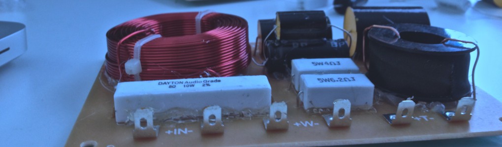
I decided to try to do some of my own measurements on the BR-1 kit I build so I headed out to the lab.
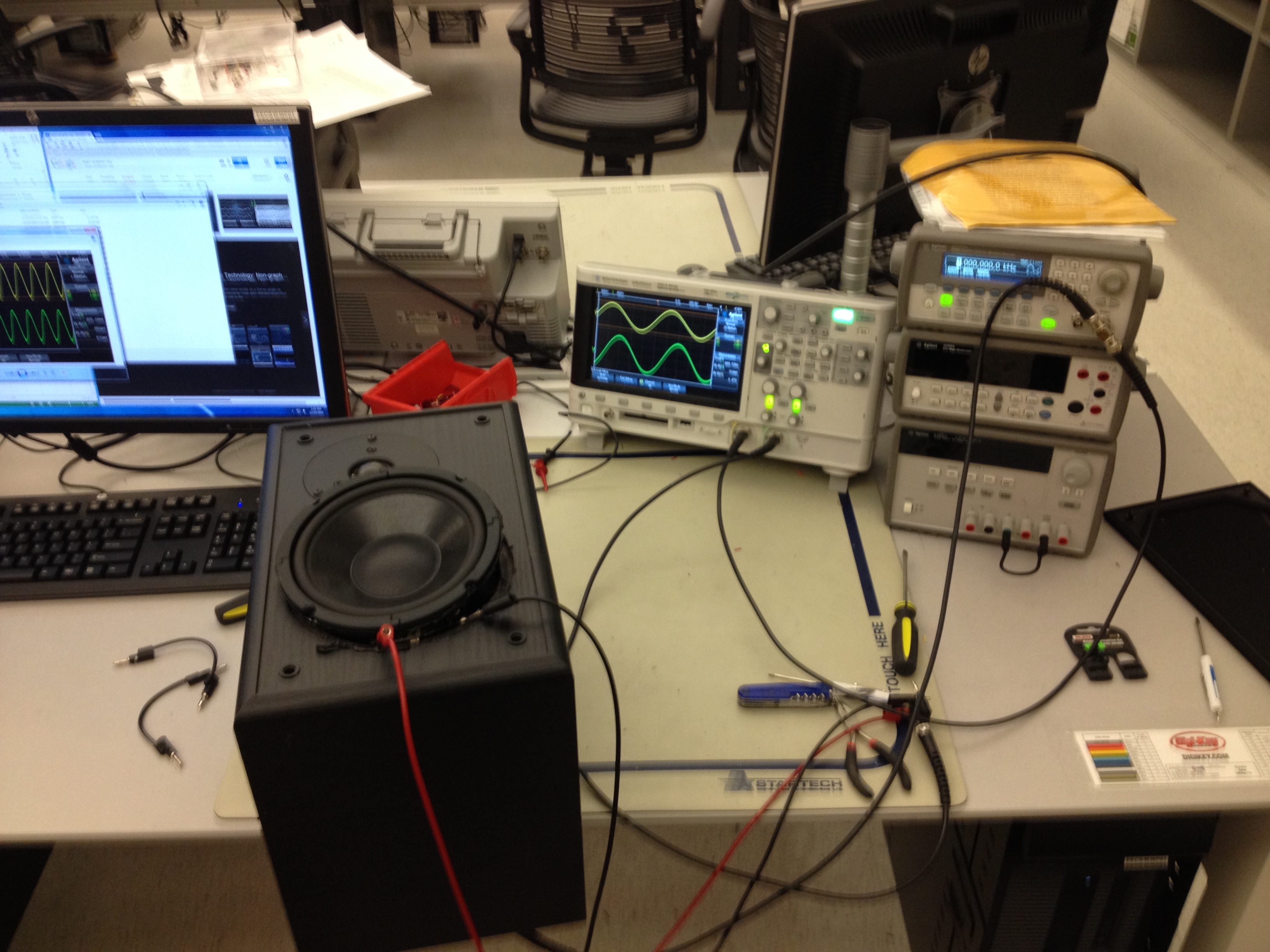
I sent a sinusoidal signal from the function generator to both the oscilloscope and to my speaker.

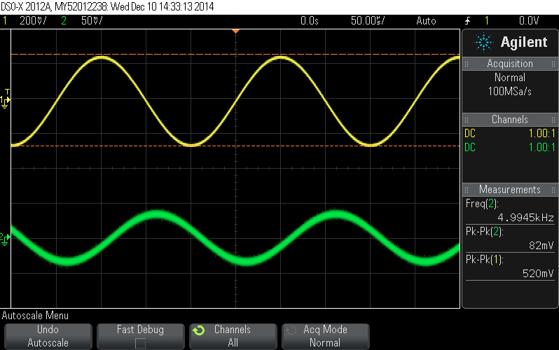
I then measured the voltage over the woofer, and then over the tweeter while changing the frequency of the input.
I recorded the data from the oscilloscope.
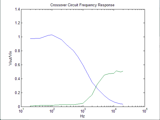
Using Excel and Matlab, I plotted the ratio of the input peak-to-peak voltage to the output peak-to-peak voltage.
Here is the figure given in the BR-1 manual for the frequency response of the individual drivers and the summed system response.
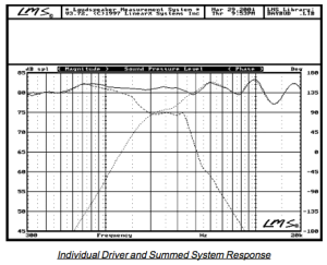
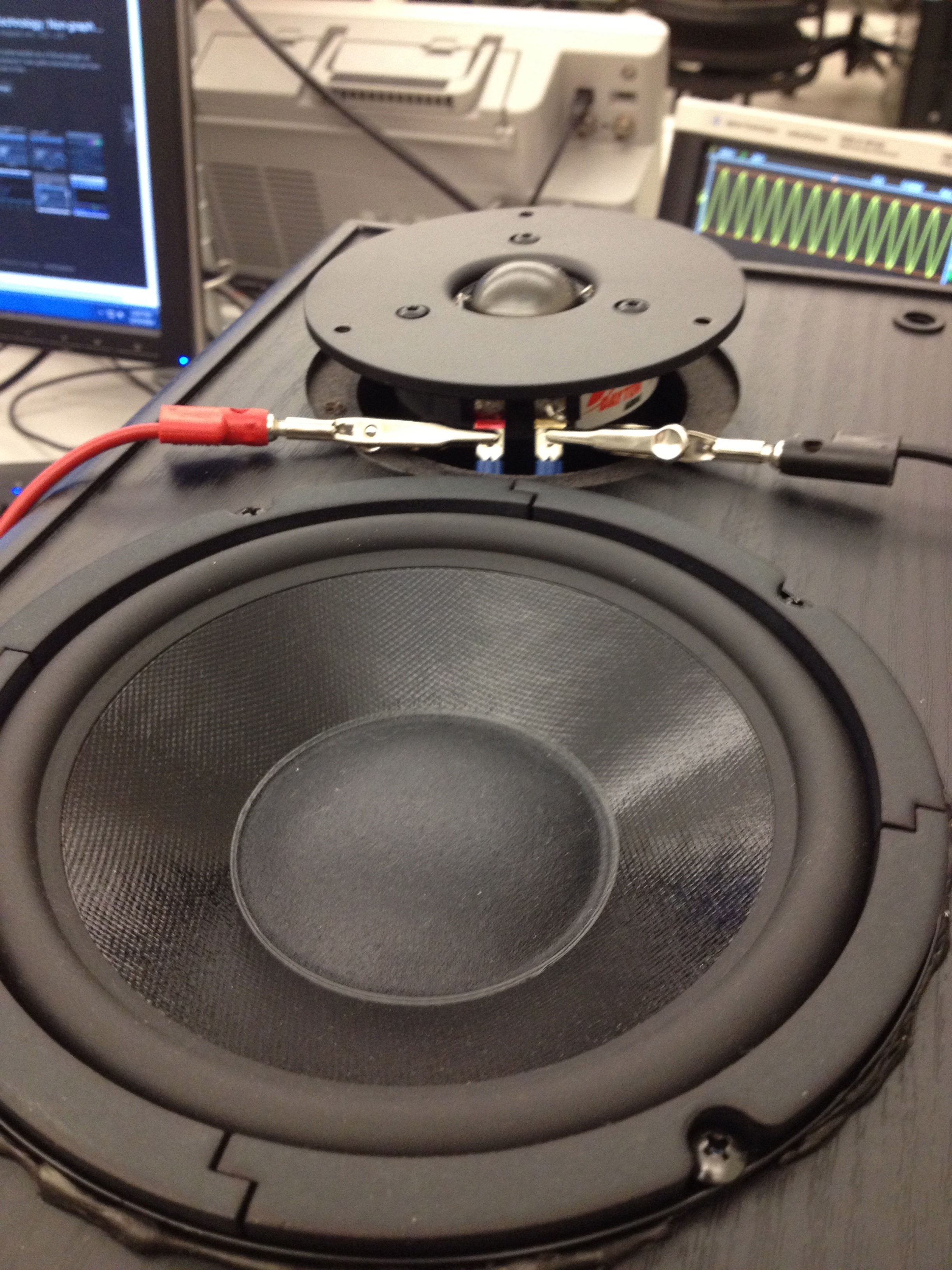
The graph above was made with a microphone placed 45″ from the tweeter of the speaker. The acoustic crossover frequency occurs at 2.1kHz. My measurements show the crossover frequency to be closer to 3kHz, however, there are a few reasons to believe my measurements have some error. The impedance of the driver depends on the amount of force required to move the speaker cone, and the amount of force required to move the speaker cone is probably different when the driver is mounted to an airtight cabinet. In order to get access to the driver and crossover circuit, I had to partially remove the woofer and tweeter from the cabinet. I believe that this caused significant error in my measurements. Still, it was satisfying to demonstrate the general contour of the crossover circuit on my own.
